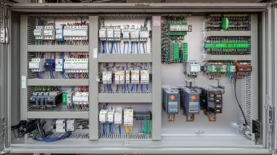
How to Choose the Right Electrical Control Panel?

Choosing the right electrical control panel begins with understanding the machine, building, and people using it. A panel that looks suitable on paper may fail in a dusty workshop, a humid plant room, or a crowded production line. Experienced engineers examine voltage, current, motor loads, short-circuit levels, enclosure ratings, and available space before recommending a design. The operating environment matters.

Clear specifications prevent expensive surprises. Confirm the incoming supply, control voltage, heat dissipation, cable entries, communication protocols, and future expansion needs. An enclosure rated for the environment can protect sensitive components from water, dust, oil, and accidental contact. However, an impressive rating cannot correct poor ventilation or careless cable routing. Small details matter.

Reliable selection also depends on standards, documentation, and verification. Reputable manufacturers should provide wiring diagrams, component data, inspection records, and test evidence. Depending on the application and region, designers may reference IEC 61439, relevant electrical codes, and local safety requirements. Independent inspection can reveal loose terminals, inadequate labeling, or an underrated protective device before commissioning. That evidence deserves attention.

Practical experience should guide the final decision. Ask how technicians will isolate power, replace a contactor, read a fault message, or clean the enclosure at midnight. A compact panel may save space but restrict maintenance access. A low-cost panel may appear efficient but create higher downtime later. No panel is perfect. Good decisions balance safety, performance, maintainability, cost, and honest risk assessment. This guide explains how to compare those factors and select an electrical control panel with greater confidence.
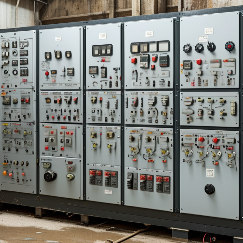
How to Choose the Right Electrical Control Panel?

Define Voltage, Current, Load, and Fault Requirements Under IEC 61439

Choosing the right electrical control panel starts with measurable requirements, not enclosure size. IEC 61439 requires a clear definition of the assembly’s operating conditions and verification responsibilities. Begin with the system voltage, including nominal voltage, frequency, earthing arrangement, and overvoltage category. Confirm the rated operational voltage, Ue, matches every connected circuit.

Current selection needs more than adding nameplate values. Record the rated current of each circuit, the assembly rated current, InA, and the expected load profile. Motor starting currents, heaters, control transformers, and future spare capacity can change the result. Apply a realistic rated diversity factor, RDF. A panel may carry many loads, but rarely at full demand simultaneously.

Load details should include duty cycles, ambient temperature, altitude, enclosure protection, and cable entry conditions. Heat inside a crowded cabinet is easy to underestimate. Fault requirements deserve equal attention. Calculate the prospective short-circuit current at the installation point, then compare it with the panel’s verified short-time and peak withstand ratings, such as Icw and Ipk. Check protective-device coordination and the required disconnection time.

A practical design review should trace every value back to a drawing, calculation, or test record. Small errors matter. A 400 V system, a 630 A incomer, and a 35 kA fault level describe different design limits. Do not treat them as interchangeable. Leave room for questioning assumptions, because the first load schedule is often incomplete.

Match Enclosure Protection to the Environment with IEC 60529 IP Ratings

How to Choose the Right Electrical Control Panel?

Match Enclosure Protection to the Environment with IEC 60529 IP Ratings

An electrical control panel should fit its environment, not merely its equipment list. IEC 60529 IP ratings provide a practical way to assess enclosure protection against solids and water. The first digit indicates protection from solid objects and dust. The second digit describes resistance to water exposure.

For example, IP54 can suit a clean indoor area with limited splashing. IP65 offers dust-tight protection and resistance to water jets. IP67 supports temporary immersion, but it does not automatically guarantee protection against powerful water jets. That detail is often missed. In demanding washdown areas, the enclosure may need a rating tested for both conditions.

Look beyond the rating label. Check cable glands, door seals, hinges, ventilation openings, and mounting orientation. A small gap around a cable can weaken the entire protection system.

Condensation also deserves attention, especially when warm panels cool overnight. Drains, breathers, or internal heaters may be necessary.

IP ratings do not fully address corrosion, ultraviolet exposure, chemical vapors, or impact strength. Site conditions can be less predictable than specifications suggest.

A panel near salt spray may require suitable materials and coatings, even with a high IP rating. Review the actual cleaning method, temperature, spray pressure, and immersion risk before selecting the enclosure.

A higher number is not always the better answer.

Size Busbars and Breakers for Available Fault Current and UL 508A SCCR

How to Choose the Right Electrical Control Panel?

Selecting an electrical control panel begins with the available fault current at its installation point. In panel design reviews, I have seen teams choose breakers by load current alone. That approach misses the short-circuit risk. The available fault current may be far higher than the normal operating current. Obtain the utility data, transformer impedance, and upstream protection information before sizing components.

Busbars must withstand the expected fault energy without melting, deforming, or creating unsafe clearances. Their material, cross-sectional area, spacing, supports, and connection points all affect performance. Breakers also need suitable interrupting ratings for the available fault current. A breaker that handles the load may still be unsuitable during a fault. Small details matter.

UL 508A SCCR evaluates the panel as an assembly, not as a collection of isolated parts. The final SCCR can be limited by the weakest component, including motor starters, terminal blocks, disconnects, or supplementary protectors. Use documented combinations and follow the applicable construction requirements. Current-limiting protection may improve the calculated result, but only when its conditions are satisfied.

Keep records. They matter later.

Label the panel with the correct SCCR and verify the calculation. A tidy schematic does not prove a reliable design. I have also learned that rushed assumptions about transformer data can undermine an otherwise careful panel. Recheck field conditions, conductor lengths, and protective-device settings before release. Safety margins should be deliberate, not accidental.

Select Controls and Networks for 50/60 Hz Industrial Power Systems

How to Choose the Right Electrical Control Panel?

Selecting controls for 50/60 Hz industrial power systems begins with the equipment’s real operating conditions. Confirm voltage, phase configuration, motor load, fault current, and frequency before choosing components. A 50 Hz motor can run differently on a 60 Hz supply, affecting speed, torque, and heating. Do not rely on a familiar panel design.

Specify circuit protection with adequate interrupting capacity and coordination. Check the panel’s short-circuit rating against the available fault current. Enclosure protection also matters. Dust, oil mist, condensation, and washdown areas may require different enclosure ratings. Leave practical space around drives, relays, and power supplies. Crowded wiring creates heat and troubleshooting delays.

The control network should match the process, not just the purchasing preference. Industrial Ethernet can support diagnostics and fast data exchange, while simpler serial links may suit isolated equipment. Define cable routes, shielding, grounding, switch placement, and network segmentation early. Redundant paths may protect critical production, but they add configuration and maintenance demands. Test communication during commissioning, including loss of power and incorrect device settings.

Field experience shows that frequency assumptions are often missed. A panel may pass a factory test yet behave poorly after installation. Review protective settings with a qualified engineer and verify them under actual load. Keep drawings, terminal labels, firmware records, and test results accessible. Some designs look efficient on paper. They may not be easy to service.

How to Choose the Right Electrical Control Panel? - Select Controls and Networks for 50/60 Hz Industrial Power Systems

Selection Dimension Typical Industrial Requirement 50 Hz Consideration 60 Hz Consideration Recommended Design Check
System frequency 50 Hz or 60 Hz, three-phase industrial supply Confirm that transformers, motors, timers, meters, and protective devices are rated for 50 Hz. Confirm that transformers, motors, timers, meters, and protective devices are rated for 60 Hz. Do not assume a 50 Hz component is suitable for 60 Hz, or vice versa; verify the nameplate frequency range.
Nominal system voltage Common low-voltage systems include 208, 220, 230, 240, 380, 400, 415, 440, 480, and 600 V AC. Voltage and frequency must match the local utility supply and connected loads. Voltage and frequency must match the local utility supply and connected loads. Specify line-to-line voltage, line-to-neutral voltage, phase arrangement, grounding method, and permitted voltage tolerance.
Incoming current rating Typical control and distribution panels may range from approximately 16 A to 4,000 A, depending on the installation. Calculate current from the 50 Hz load profile, including motor starting and transformer energization. Calculate current from the 60 Hz load profile, including motor starting and transformer energization. Apply continuous-load requirements, diversity factors, future capacity, and the applicable electrical code.
Short-circuit withstand Panel short-circuit rating must be equal to or greater than the available fault current at the installation point. Frequency can affect the performance of protective and switching equipment; use tested ratings for the intended frequency. Frequency can affect the performance of protective and switching equipment; use tested ratings for the intended frequency. Obtain the utility or transformer fault-current study and verify the panel SCCR or prospective short-circuit withstand rating.
Enclosure protection Indoor clean areas generally require a basic protected enclosure; dust, water, oil, and outdoor exposure require higher protection. Frequency does not replace the need for environmental protection. Frequency does not replace the need for environmental protection. Select an enclosure classification such as IP54, IP55, IP65, or the applicable NEMA type based on dust, moisture, corrosion, and washdown exposure.
Control voltage Common control circuits use 24 V DC, 110/120 V AC, or 220/230 V AC. Control transformers and AC coils must be rated for 50 Hz unless specifically marked for both frequencies. Control transformers and AC coils must be rated for 60 Hz unless specifically marked for both frequencies. Use 24 V DC where reduced shock risk, PLC compatibility, and stable instrumentation power are priorities.
Motor-control method Options include direct-on-line starters, soft starters, and variable-frequency drives. Motor speed is approximately proportional to frequency; a 50 Hz motor normally has a lower synchronous speed than the same motor at 60 Hz. A 60 Hz motor generally operates at a higher synchronous speed than the equivalent 50 Hz motor. Check motor nameplate frequency, rated speed, starting current, overload setting, braking method, and drive compatibility.
Busbar and wiring capacity Copper or aluminum conductors are selected according to current, temperature rise, installation method, and fault duty. Verify temperature-rise and dielectric-test data at 50 Hz where required by the applicable assembly standard. Verify temperature-rise and dielectric-test data at 60 Hz where required by the applicable assembly standard. Allow space for neutral and protective conductors, cable bending radius, heat dissipation, and future circuits.
Operating environment Typical industrial design conditions are approximately −5 °C to +40 °C ambient, subject to the selected standard and equipment ratings. Frequency has little direct effect on enclosure selection, but it affects heat losses in some magnetic components. Frequency has little direct effect on enclosure selection, but it affects heat losses in some magnetic components. Account for altitude, humidity, condensation, vibration, corrosive gases, indoor or outdoor location, and solar heating.
Compliance framework The applicable requirements depend on the country, installation type, and authority having jurisdiction. IEC-based installations commonly specify rated operational voltage, current, frequency, and assembly verification. North American installations commonly require equipment and installation ratings appropriate to the local electrical code. Identify the governing standard before design; coordinate labeling, testing, protection, grounding, and documentation requirements.
Future expansion Industrial loads often change as production capacity increases or new automation is installed. Reserve capacity should support the expected 50 Hz load growth. Reserve capacity should support the expected 60 Hz load growth. Consider 15–25% spare panel space and spare capacity only when permitted by the load calculation and fault-current study.
Selection note: Final panel ratings must be confirmed from the site voltage and frequency, connected-load schedule, available fault current, environmental conditions, applicable code, and verified equipment documentation.

Verify NEC Article 409 Compliance, Testing, and Documentation Before Installation

How to Choose the Right Electrical Control Panel?

Before installation, verify that the panel fits NEC Article 409. The article addresses industrial control panels, including enclosure markings, wiring methods, and short-circuit current rating (SCCR). Do not guess. Confirm the available fault current at the installation point, then compare it with the panel’s marked SCCR. A mismatch can create a serious protection problem.

Testing should be documented, not treated as a final formality. Record conductor continuity, insulation resistance, grounding connections, protective-device settings, and functional test results. Use qualified personnel and calibrated instruments. ESFI reported 126 workplace electrical fatalities and 2,460 nonfatal electrical injuries in 2020. Those figures cover many equipment types, but they show why verification deserves time. Keep it visible.

Documentation must follow the panel from design to maintenance. Include the one-line diagram, load calculations, SCCR basis, wiring drawings, component instructions, test dates, and approved changes. NFPA 70E emphasizes risk assessment, training, and electrically safe work practices, while Article 409 focuses on panel construction and marking. These requirements support each other, but they are not interchangeable. A neat drawing can still hide a wrong SCCR assumption. Recheck field conditions. That gap matters.

Scroll to Top