
What Is Ultra Wideband Positioning and How Does It Work?
Ultra Wideband Positioning is a precise wireless method for locating people, tools, and equipment indoors. It uses extremely short radio pulses to measure distance between a small tag and fixed anchors. These measurements can produce location data within a few centimeters in suitable conditions. GPS often struggles inside buildings. UWB can continue working where concrete walls block satellite signals.
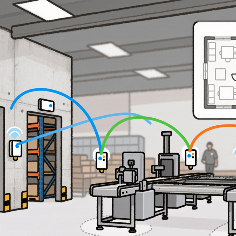
The process depends on timing. A tag sends a pulse, and anchors record when it arrives. The system calculates distance from the signal’s travel time. Some networks use two-way ranging, while others compare arrival times across multiple anchors. Software then combines these distances to estimate the tag’s position. A worker might carry a badge, while anchors sit near doorways, ceilings, or production lines. The resulting map can show movement through a warehouse almost in real time.
Accuracy is not automatic. Metal shelves, moving bodies, poor anchor placement, and clock errors can distort results. Calibration matters. So does thoughtful installation. Modern UWB solutions may use security features associated with IEEE 802.15.4z, but implementation quality still varies. Privacy also requires careful decisions about data retention and user consent. This technology is powerful, yet it is not magic. A few centimeters in a laboratory may become tens of centimeters on a crowded factory floor. This guide explains how Ultra Wideband Positioning works, where it performs well, and why practical testing remains essential. Some assumptions may fail in unfamiliar buildings. That is worth remembering.
What Ultra-Wideband Positioning Means
Ultra-wideband positioning means locating objects or people through very short radio pulses. Unlike systems that estimate distance from signal strength, UWB measures how long a pulse takes to travel. The result can be accurate to roughly tens of centimeters in suitable conditions. That sounds simple, but real spaces are rarely simple.
A positioning system usually includes fixed anchors and mobile tags. Anchors sit around a room, while a tag sends signals between them. The system calculates distance from signal travel time, then combines several measurements to estimate location. Walls, metal surfaces, crowded rooms, and poor anchor placement can reduce accuracy. Reflected signals may also create unstable readings. Calibration matters more than many quick demonstrations suggest. Even then, small errors remain.
Tips: Place anchors at different heights and keep them away from large metal objects. Test accuracy while people move through the space. Record errors, not only successful results. Use UWB for clear location data, but avoid treating every measurement as perfect. A backup sensor can improve reliability when signals become blocked.

The Core Signals and Hardware Behind UWB
What Is Ultra Wideband Positioning and How Does It Work?
The Core Signals and Hardware Behind UWB
Ultra-wideband positioning starts with very short radio pulses, not a steady carrier tone. Their broad spectrum helps a receiver distinguish direct arrivals from later reflections. In U.S. rules, an UWB signal has a bandwidth of at least 500 MHz, or a fractional bandwidth of at least 20 percent (47 CFR §15.503). That spread is useful indoors, where walls and metal fixtures scatter radio energy. It is not magic. A blocked direct path can still distort a distance estimate.
A typical system uses a small radio antenna, a precise clock, and processing hardware that timestamps pulse exchanges. Two devices can estimate distance from signal travel time; multiple fixed anchors can then help calculate a tag’s position. FiRa Consortium’s UWB technology overview describes ranging precision of up to about 10 centimeters in suitable conditions. Real rooms are less tidy. A person walking between devices, a metal cabinet, or poor anchor placement may reduce accuracy. The clock matters, too: tiny timing errors become meaningful distance errors because radio pulses travel extremely fast. Engineers therefore test the whole setup, not just the radio chip. That detail is easy to overlook.
How UWB Calculates Location Step by Step
What Is Ultra Wideband Positioning and How Does It Work?
How UWB Calculates Location Step by Step
Ultra Wideband positioning uses very short radio pulses to estimate distance. A mobile tag sends a signal to fixed anchors, or the anchors respond to the tag. The system records precise transmission and reception times. Even a tiny timing error matters.
The calculation begins with time of flight. The signal’s travel time is multiplied by the speed of light, producing an estimated distance. Some systems use two-way ranging, where a signal travels out and back. Others compare arrival times across synchronized anchors. Each distance creates a circle around an anchor. The tag’s position appears where several circles intersect.
That sounds simple.
In practice, the positioning engine uses at least three anchors for two-dimensional location, and more for stronger three-dimensional results. It applies multilateration, then filters unstable readings caused by walls, metal surfaces, or blocked paths. Poor anchor placement can distort the result, even with excellent hardware. Engineers should check calibration, clock behavior, antenna orientation, and line of sight during installation. A single reflected pulse may move the estimate by several centimeters or more. The system can reject that reading, but filtering may also hide genuine movement. Reliability comes from repeated testing, sensible geometry, and honest attention to those imperfect measurements.
What Is Ultra Wideband Positioning and How Does It Work? - How UWB Calculates Location Step by Step
| Step | Positioning Stage | How It Works | Key Data and Technical Facts |
|---|---|---|---|
| 1 | Define the Positioning Environment | The system establishes a local coordinate area and identifies the fixed reference points, called anchors, and the moving devices, called tags. | Anchors have known coordinates, such as (x, y) or (x, y, z). A tag is the object whose location must be calculated. Two-dimensional positioning generally requires at least three suitable distance measurements, while three-dimensional positioning normally requires at least four. |
| 2 | Transmit a UWB Radio Signal | A UWB device sends very short radio pulses across a wide frequency range. The short duration creates fine timing detail that can be used for ranging. | Ultra-wideband is commonly associated with a radio bandwidth of at least 500 MHz or a fractional bandwidth of at least 20%. UWB pulses typically occupy only a few nanoseconds or less, depending on the implementation. |
| 3 | Exchange Timestamped Messages | The tag and anchors exchange messages containing precise transmission and reception timestamps. The system uses these timestamps to estimate how long the signal traveled. | A message exchange may use one-way time of flight, two-way ranging, single-sided two-way ranging, or double-sided two-way ranging. Double-sided exchanges help reduce errors caused by clock offset between devices. |
| 4 | Measure Time of Flight | The signal travel time is estimated from the timestamp difference between transmission and reception. In two-way ranging, the signal travels from one device to another and back. | The basic relationship is distance = signal travel time × speed of light. Radio signals travel at approximately 299,792,458 meters per second in a vacuum. A 1-nanosecond timing error corresponds to roughly 0.30 meters of distance error. |
| 5 | Convert Time into Distance | The measured time of flight is converted into a range between the tag and each anchor. Each range represents a possible circle or sphere around an anchor. | For an ideal one-way measurement, d = c × Δt. For a round-trip measurement, the calculated distance is approximately d = c × (round-trip time − device processing delay) ÷ 2. Antenna delays and calibration values must be compensated. |
| 6 | Detect the First Path | The receiver analyzes the incoming waveform to identify the earliest valid signal path, rather than using only the strongest received reflection. | The first arriving path is important because reflected paths travel farther. Direct line-of-sight conditions usually provide the most reliable range. Walls, metal, furniture, people, and other objects can create multipath and non-line-of-sight errors. |
| 7 | Perform Trilateration or Multilateration | The location engine intersects the measured ranges from multiple anchors. In two dimensions, each range forms a circle; in three dimensions, each range forms a sphere. | For an unknown point (x, y) and anchor (xᵢ, yᵢ), the range equation is (x − xᵢ)² + (y − yᵢ)² = dᵢ². With more measurements than the minimum, the system can use least-squares or weighted optimization to reduce noise. |
| 8 | Estimate the Position | The positioning algorithm solves the range equations and produces the tag's coordinates in the local reference frame. | The result may include x, y, and optionally z coordinates, together with quality indicators such as residual error, anchor count, signal quality, and line-of-sight status. |
| 9 | Apply Filtering and Sensor Fusion | Successive position estimates are smoothed to reduce jitter. Motion sensors can be combined with UWB ranging to maintain a more stable track between updates. | Common processing methods include moving averages, Kalman filters, and extended Kalman filters. Accelerometers and gyroscopes can help estimate motion, while UWB corrects accumulated inertial drift. |
| 10 | Report Accuracy and Update Rate | The final location is delivered to an application together with timing and quality information. Accuracy depends on geometry, calibration, obstructions, antenna placement, and algorithm settings. | Well-designed indoor UWB systems can commonly achieve decimeter-level positioning under favorable conditions. Practical performance varies by environment. Higher update rates improve responsiveness but can increase power consumption and network traffic. |
Important limitation: UWB measures distance and timing very accurately, but the final position also depends on anchor placement, synchronization, antenna calibration, signal blockage, multipath, and the quality of the location algorithm.
Main UWB Positioning Methods and System Designs
Ultra-wideband positioning uses very short radio pulses to measure distance and time. Its practical value depends on system design, not frequency alone. In a two-way ranging system, a tag exchanges messages with an anchor and estimates distance from signal travel time. This works well in warehouses, but clock delays and metal shelving still create errors.
Time difference of arrival uses several synchronized anchors. The tag’s position comes from differences between arrival times, reducing the need for a reply message. Angle of arrival adds antenna arrays, allowing the system to estimate direction as well as distance. Hybrid designs combine these methods with inertial sensors. They can maintain smoother tracking when a person briefly blocks the radio path. That assumption is convenient, and often wrong.
A typical deployment includes tags, fixed anchors, a synchronization layer, a positioning engine, and an application interface. Anchor geometry matters. Four anchors in one corridor may perform worse than three well-spaced anchors around a work area. NIST technical guidance identifies multipath and non-line-of-sight conditions as major indoor positioning risks. Real installations therefore need site surveys, calibration, and confidence scores. Market data also signals growing demand: Grand View Research estimated the UWB market at about USD 1.6 billion in 2023, while MarketsandMarkets forecasts strong double-digit growth through 2028. Those forecasts describe opportunity, not guaranteed accuracy. A practical design should test concrete cases: a worker behind a shelf, a tag inside a metal cart, or one anchor losing power. Imperfect conditions are normal.
UWB Positioning Methods: Typical Indoor Accuracy
Representative positioning error ranges under favorable indoor, line-of-sight conditions. Actual results vary with anchor geometry, multipath, synchronization, and system setup; lower error is better.
Two-way ranging (TWR) estimates distance from signal round-trip time. Time-difference-of-arrival (TDoA) uses arrival-time differences at synchronized anchors. Angle-of-arrival (AoA) estimates direction from signals received by antenna arrays. These methods can be combined in hybrid systems.
Practical Uses, Strengths, and Limitations of UWB
Ultra Wideband (UWB) positioning calculates distance from tiny differences in radio signal travel time. A tag exchanges brief pulses with fixed anchors around a room. Software combines these measurements to estimate the tag’s location, often in three dimensions. Unlike signal-strength methods, UWB relies mainly on timing, not signal loudness. In practical tests, it can deliver decimeter-level accuracy under favorable conditions. It is not magic.
Warehouses use UWB to locate tools, pallets, and workers within defined zones. Hospitals can track mobile equipment, reducing time spent searching empty corridors. Smart buildings may use it for room-level navigation, lighting control, and access decisions. Robots can treat UWB as one positioning input indoors. Its strongest benefit is precision with low latency. Moving tags can update quickly. That matters near doors, vehicles, or machinery.
However, performance depends heavily on installation. Metal shelves, concrete, people, and narrow passages can reflect or block signals. Poor anchor placement may create confident but incorrect coordinates. Calibration takes effort, and batteries limit small tags. UWB hardware also costs more than basic proximity systems. Privacy needs attention when location data follows people for long periods. Encryption helps, but it cannot replace clear policies. In crowded spaces, accuracy may drift more than expected. A pilot with error logs is wiser than trusting a brochure.

