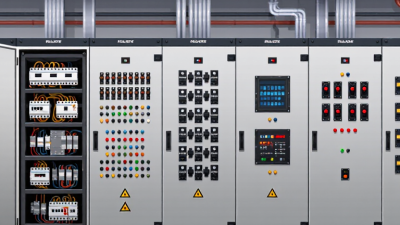
How to Design an Electrical Control Panel in 2026?
Designing an electrical control panel in 2026 is no longer a simple exercise in arranging breakers, terminals, and contactors. It is a practical balance between safety, uptime, cybersecurity, energy efficiency, and future expansion. The panel may sit quietly against a factory wall, yet it controls motors, sensors, drives, and production decisions every second.
Industry data shows why the design process is changing. Rockwell Automation’s State of Smart Manufacturing Report 2024 found that 95% of manufacturers surveyed had invested in, or planned to invest in, artificial intelligence and machine learning within five years. That investment increases the need for reliable industrial networks, cleaner wiring, better diagnostics, and structured data access. Deloitte’s 2024 Smart Manufacturing and Operations Survey also identified measurable performance gains from connected operations, including improvements in production output, productivity, and capacity. These gains depend on physical infrastructure that engineers can maintain.
Standards still anchor professional judgment. IEC 60204-1 addresses electrical equipment of machines, while UL 508A supports industrial control panel construction in applicable North American installations. NFPA 79 adds important machine-safety guidance. Local requirements must be verified.
Details matter. A loose ferrule, crowded wire duct, or poorly labeled terminal can delay troubleshooting at 2 a.m. I have seen elegant drawings fail in the field because heat, vibration, and access were treated as minor issues. That is uncomfortable, but useful. Good electrical control panel design leaves space, documents assumptions, and challenges its own first solution. The following guide examines sizing, enclosure selection, protection, PLC architecture, thermal management, testing, and maintainability for 2026 projects.
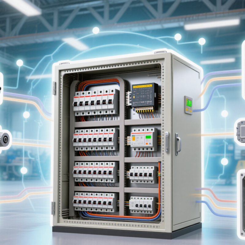
Define Requirements Under IEC 61439: Up to 1,000 V AC or 1,500 V DC
How to Design an Electrical Control Panel in 2026?
Design begins with a precise voltage boundary. IEC 61439 covers assemblies up to 1,000 V AC or 1,500 V DC. Record the system voltage, rated current, frequency, and earthing arrangement. These values influence insulation, clearances, protective devices, and conductor sizing. Do not treat voltage as a label only. A higher fault level can change the entire enclosure design.
Define short-circuit withstand requirements before selecting busbars. Check temperature-rise limits, enclosure protection, internal separation, and mechanical strength. Specify the expected environment, including dust, moisture, heat, and vibration. A panel may pass a visual inspection while failing under sustained load. I have seen neat layouts conceal poor terminal access and crowded wiring. That mistake deserves more attention. Keep power and control circuits clearly arranged, with dependable protective bonding and labeled conductors. Document design calculations and verification results under the applicable IEC 61439 procedures.
Tips:
Leave space for heat dissipation and future wiring. Confirm cable bending radii at the design stage. Use ferrules, torque records, and durable labels. Review door movement before installing components. Photograph critical connections during inspection. An independent technical review can reveal assumptions that the original designer missed. Small details matter.
Size Conductors for 125% Continuous Loads Under NFPA 70
How to Design an Electrical Control Panel in 2026?
A reliable panel begins with an accurate load schedule. Under NFPA 70, a continuous load operates for three hours or longer. Its calculated value must be multiplied by 125%. For example, a 32-ampere heater requires at least 40 amperes of conductor ampacity before adding noncontinuous loads. Do not size from the breaker alone. Check terminal temperature ratings, ambient temperature, conduit fill, and adjustment factors.
Then verify the complete circuit path. Conductor ampacity must satisfy the feeder or branch-circuit rule in the adopted NFPA 70 edition. A 75°C conductor rating may be usable only when connected equipment permits it. Panel bus rating, short-circuit current rating, and overcurrent protection also need independent checks. Voltage drop deserves attention, especially with long control runs. A calculation can pass ampacity rules and still produce unreliable coils or sensors.
The demand is becoming less predictable. The U.S. Energy Information Administration’s 2018 Commercial Buildings Energy Consumption Survey reported that electricity supplied about 60% of commercial building site energy. More electrified equipment can increase continuous loads inside compact panels. NFPA’s electrical fire research also continues to identify distribution equipment as a recurring ignition concern. That makes heat mapping valuable. I prefer recording measured current after commissioning, not trusting assumptions forever. Small mistakes happen. A loose terminal, underestimated ambient temperature, or missing future load can invalidate an otherwise careful design. Verify the locally adopted code edition and document every calculation.
How to Design an Electrical Control Panel in 2026? - Size Conductors for 125% Continuous Loads Under NFPA 70
| Design Item | Example Value | Calculation or Selection Basis | Recommended Conductor | 75°C Ampacity | Design Check |
|---|---|---|---|---|---|
| Continuous-Load Conductor Sizing Examples | |||||
| Branch control circuit | 8 A continuous load | 8 A × 125% = 10 A minimum conductor ampacity | 14 AWG copper THHN/THWN-2 | 20 A | Passes the minimum 10 A ampacity requirement, subject to terminal, ambient-temperature, and adjustment-factor limitations. |
| Small motor-control load | 16 A continuous load | 16 A × 125% = 20 A minimum conductor ampacity | 12 AWG copper THHN/THWN-2 | 25 A | Passes the minimum 20 A ampacity requirement. |
| Heater or process-control load | 24 A continuous load | 24 A × 125% = 30 A minimum conductor ampacity | 10 AWG copper THHN/THWN-2 | 35 A | Passes the minimum 30 A ampacity requirement. |
| Panel feeder | 40 A continuous load | 40 A × 125% = 50 A minimum conductor ampacity | 8 AWG copper THHN/THWN-2 | 50 A | Meets the minimum conductor ampacity exactly before any derating or other correction. |
| Control-panel feeder | 52 A continuous load | 52 A × 125% = 65 A minimum conductor ampacity | 6 AWG copper THHN/THWN-2 | 65 A | Meets the minimum conductor ampacity exactly before any derating or other correction. |
| Large process-panel feeder | 68 A continuous load | 68 A × 125% = 85 A minimum conductor ampacity | 4 AWG copper THHN/THWN-2 | 85 A | Meets the minimum conductor ampacity exactly before any derating or other correction. |
| High-capacity feeder | 92 A continuous load | 92 A × 125% = 115 A minimum conductor ampacity | 2 AWG copper THHN/THWN-2 | 115 A | Meets the minimum conductor ampacity exactly before any derating or other correction. |
| Industrial control-panel feeder | 120 A continuous load | 120 A × 125% = 150 A minimum conductor ampacity | 1/0 AWG copper THHN/THWN-2 | 150 A | Meets the minimum conductor ampacity; verify equipment termination ratings and installation conditions. |
| Reference Ampacity and Design Dimensions | |||||
| 14 AWG copper | 20 A at 75°C | Typical minimum size for a 10 A calculated ampacity requirement | 14 AWG copper THHN/THWN-2 | 20 A | Do not exceed the allowable ampacity after all applicable corrections and adjustments. |
| 12 AWG copper | 25 A at 75°C | Typical minimum size for a 20 A calculated ampacity requirement | 12 AWG copper THHN/THWN-2 | 25 A | Commonly used for a 20 A design requirement when all installation conditions permit. |
| 10 AWG copper | 35 A at 75°C | Typical minimum size for a 30 A calculated ampacity requirement | 10 AWG copper THHN/THWN-2 | 35 A | Verify the selected overcurrent protective device and equipment terminal limitations. |
| 8 AWG copper | 50 A at 75°C | Typical minimum size for a 50 A calculated ampacity requirement | 8 AWG copper THHN/THWN-2 | 50 A | Any ambient-temperature or conductor-bundling adjustment may require a larger conductor. |
| 6 AWG copper | 65 A at 75°C | Typical minimum size for a 65 A calculated ampacity requirement | 6 AWG copper THHN/THWN-2 | 65 A | Confirm conductor routing, terminal temperature rating, and available fault current. |
| 4 AWG copper | 85 A at 75°C | Typical minimum size for an 85 A calculated ampacity requirement | 4 AWG copper THHN/THWN-2 | 85 A | Verify the complete feeder design, including voltage drop where applicable. |
| 2 AWG copper | 115 A at 75°C | Typical minimum size for a 115 A calculated ampacity requirement | 2 AWG copper THHN/THWN-2 | 115 A | Equipment rated 100 A or more generally requires use of the applicable 75°C ampacity column unless a specific exception applies. |
| 1/0 AWG copper | 150 A at 75°C | Typical minimum size for a 150 A calculated ampacity requirement | 1/0 AWG copper THHN/THWN-2 | 150 A | Confirm lug range, termination temperature rating, conductor bending space, and enclosure dimensions. |
| Panel Design Verification Dimensions | |||||
| Continuous-load factor | 125% | Minimum conductor ampacity = noncontinuous load + 125% of continuous load | Apply to each applicable feeder or branch circuit | Not applicable | For a circuit with only continuous load, multiply the load by 1.25. |
| Voltage-drop design target | 3% branch circuit; 5% feeder plus branch circuit | Common engineering design targets used to support satisfactory equipment performance | Increase conductor size when required | Not applicable | Voltage-drop limits may be recommendations rather than mandatory limits for every installation; follow the adopted code and project specifications. |
| Conductor temperature basis | 75°C where permitted | Use the temperature column allowed by the equipment, conductor insulation, and applicable installation rules | THHN/THWN-2 copper examples | Based on 75°C column | The conductor insulation rating cannot override a lower terminal or equipment rating. |
| Adjustment-factor review | Required when conductors are grouped or exposed to heat | Apply correction and adjustment factors after identifying the applicable ampacity | Upsize conductor when the adjusted ampacity is insufficient | Varies by installation | Count current-carrying conductors and evaluate ambient temperature, raceway fill, and enclosure conditions. |
| Short-circuit withstand | Must be coordinated with available fault current | Verify panel short-circuit current rating and protective-device interrupting rating | Coordinate all panel components | Not applicable | The panel assembly and its components must be suitable for the available fault current at the installation point. |
Select UL 508A Components and Verify SCCR Against Fault Current
How to Design an Electrical Control Panel in 2026?
A reliable control panel begins with the available fault current, not the enclosure layout. Gather transformer impedance, feeder length, conductor size, and utility data. Then calculate the prospective short-circuit current at the panel terminals. The panel’s SCCR must meet or exceed that value. UL 508A Supplement SB provides the recognized method for determining panel SCCR. A neat schematic can still hide a weak assumption.
Select components evaluated for industrial control panels, including disconnects, overcurrent devices, terminal blocks, contactors, and power supplies. Check each component’s short-circuit rating and coordination requirements. Do not treat a fuse or breaker rating as the complete panel SCCR. One low-rated device can reduce the assembly rating. NFPA’s 2024 U.S. Fire Loss report recorded about 1.39 million fires and approximately 3,670 civilian deaths. The report is not limited to control panels, but it reinforces the cost of careless electrical design.
Tips: Put the calculated fault current beside the SCCR on the design record. Confirm ratings at the actual voltage and frequency. Recheck the calculation after field changes. I have seen drawings updated without updating fault-current data. That mistake is easy to make. It is also preventable. Leave clear evidence for the reviewer: source data, calculation method, component ratings, and the final verification date.
Plan 24 VDC I/O, 20% Spare Capacity, and IEC 62443 Security Zones
How to Design an Electrical Control Panel in 2026?
A reliable panel starts with a clear 24 VDC I/O plan. I map every sensor, actuator, terminal, fuse, and return path before selecting hardware. This exposes voltage drops and common-return risks early. I also reserve 20% spare capacity for I/O points, terminals, power supply load, and cabinet space. The spare margin should be calculated, not guessed. My earlier designs underestimated future diagnostics. That mistake made later modifications unnecessarily crowded.
IEC 62443 adds a security view. I divide the control system into zones, such as field I/O, controller, engineering workstation, and remote access. Conduits between zones should define permitted traffic. Unused ports stay disabled. Remote connections require documented approval, strong authentication, and time-limited access.
The World Economic Forum’s Global Cybersecurity Outlook 2025 reported that 54% of large organizations identified supply-chain vulnerabilities as a major barrier to cyber resilience. A control panel is part of that chain. Its drawings, firmware records, and service accounts need equal attention.
Tips: Label spare terminals clearly. Keep safety circuits physically distinct. Test the 24 VDC load at maximum demand, not normal demand. Record every zone boundary in the electrical drawings. Review the design with an electrician and a controls engineer. Standards help, but field conditions still surprise us. That is why commissioning feedback should update the next revision.
Validate IP Ratings, Thermal Rise, EMC, and Factory Acceptance Tests
Designing an electrical control panel in 2026 requires more than arranging components neatly. The enclosure’s IP rating must match dust, water, cleaning methods, and installation conditions. Check door-gasket compression, cable glands, drain plugs, and unused openings. A small gap can invalidate an otherwise suitable enclosure. Test it.
Thermal rise deserves practical attention. Calculate heat dissipation from every device, including power supplies, drives, relays, and terminals. Compare the result with the ambient temperature and enclosure rating. Provide cooling or ventilation when necessary, but protect airflow paths from contamination. In one workshop review, the calculation looked acceptable until warm cable ducts restricted circulation. The panel passed on paper, but not comfortably in operation.
EMC performance depends on layout and installation discipline. Separate noisy power cables from sensitive signal wiring, use short bonding paths, and terminate shields according to the system design. Then define factory acceptance tests before assembly is complete. FAT procedures should cover wiring checks, insulation resistance, protective functions, alarm sequences, communication signals, and simulated fault conditions. Record measured values, not only pass or fail results. Witness testing helps expose unclear requirements early. Still, no FAT can reproduce every site condition. That limitation should remain visible in the handover documents. A careful designer leaves room for revision, because field assumptions are often incomplete.
How to Design an Electrical Control Panel in 2026?
Validate enclosure protection, thermal performance, electromagnetic compatibility, and factory acceptance before shipment. The chart shows representative temperature-rise limits from IEC 61439-1; the allowable value depends on the component location and material.
Validation checklist: Confirm the declared IP rating according to IEC 60529, verify thermal rise under the worst-case load, perform EMC tests against the applicable product or environment standard, and complete FAT checks for wiring, protective bonding, insulation, functions, interlocks, labels, and documentation.
Related Posts
-
5 Best Electrical Control Panel Suppliers for Global Buyers
-
How to Master Electrical Control Panel Design for Your Next Project
-
Electrical Control Panel Design Innovations: Insights from the 138th China Import and Export Fair 2025
-
Exploring the Evolution of Control Panels: Industry Insights and Future Trends in Automation Technology
-

Understanding PLC Control Panels: Essential Components and Their Impact on Automation Efficiency
-
How to Choose the Best Control Panel Solutions for Your Needs?